8. A.M. Transmitter (and Hetordyne Radio)
 |  |
|---|---|
 |  |
 |  |
 |  |
 |  |
 |  |
 |  |
 |  |
 |  |
 |  |
 |  |
 |
My lab group chose to construct an A.M. transmitter as our final project. For me, the first week working on the project consisted of doing a little research on radio transmission when I had the chance. It may have been about 4 or 5 hours of research in total, but between school and extracurricular activities, it took about a week to get a working concept. That left us with nothing to do one lab period, so we decided to work on the heterodyne radio that period. We finished the circuit but, were unsuccessful in getting any output other than static from our radio. We were also unable to get with our old set up of just a one station radio which made me think there could be still hope for the heterodyne radio. So I took it home and picked up soft, but audible sound from both the one station and heterodyne radio
and that is how the HET radio became sort of a side project to our project.
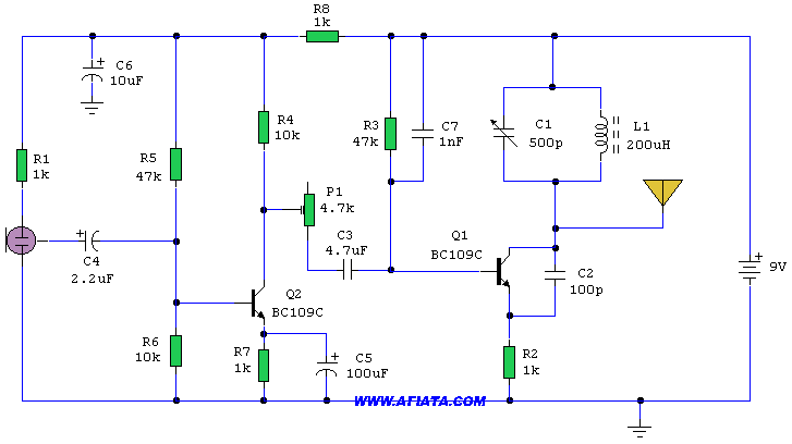
Meanwhile, I had found a few different circuit schematics for simple A.M. transmitters and one of my partners had found a chip that he could use as an oscillator to make a transmitter. Most of the schematics I found had explanations on how they were supposed to work, but I was skeptical because all of them two or less transistors. That did not seem to me to be enough for audio amplification, an oscillator, and a mixer circuit. I was also unable to completely understand the circuits due to only basic knowledge of how oscillator circuits work. Still I was willing to test them. However, it soon became clear that we wouldn't be able to obtain the parts for the circuit schematics in time to complete the project. So as an alternative, I decided to take the block diagram approach.
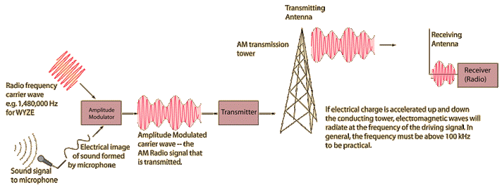
From my research, I had found a few block diagrams that showed a simple setup for A.M. transmission with low level modulation. From there, I was able to piece together an A.M. transmitter from circuits we used for the radio receiver throughout the semester. There were four modules that were needed to make the transmitter work. They were an audio amp, an oscillator, a mixer and an RF amplifier. I built most of the mixer and a Hartley oscillator and asked my partners if they had the remaining components needed for the mixer and to build an audio amp and RF amp because I had run out of parts. We had also found a simple lab for transmitting an AM signal hidden away in the lab manual. The lab allowed us to transmit using only an antenna and one of the oscillators in lab. So the next lab was spent testing the separate parts of the transmitter, taking measurements of the receiver, and testing the HET radio to verify that it still worked and could pick up a signal transmitted from the lab equipment.
To do this, we split up tasks in lab. One of my partners worked on his chip based AM transmitter and a bunch of variable resistors. After getting it to work and realizing that it did not transmit at a high enough frequency, he perfected and tested my Hartley oscillator circuit. The other partner fine-tuned and tested his audio amp. I was tasked with making measurements of the radio, picking up a signal, and transmitting a signal from my cell phone using the lab oscillator.
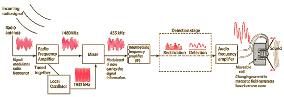
The measurements I made with of the radio included the frequency spectrum of the antenna node, the frequency spectrum of the mixer output (connected and disconnected from the bandpass filter), and the output signal of the oscillator. The antenna node frequency spectrum showed what seemed to be just noise. Though the spectrum seemed useless to measure at first glance, it proved to be useful to my understanding of the HET radio. We had left a variable capacitor in parallel with the antenna thinking that the resonant structure used for the one station radio was needed to pick up signals for the HET radio. I found this to be untrue after seeing that tuning that capacitor had little effect on the antenna node and no effect at all on the mixer output. So I took the capacitor out which made tuning the radio much less complicated.
The frequency spectrum of the mixer output without the bandpass filter show a broad range of frequencies that shifted as I tuned the variable capacitor on the Hartley Oscillator. These were the products of the different frequencies picked up by the antenna being mixed with the oscillator frequency. When I connected the output to the rest of the radio with no bandpass filter, there was no sound. My guess is that all the different frequencies end up cancelling out making each of the signals too weak to be detected.
With the bandpass filter connected, there was a single frequency on the spectrum that never moved position, but disappeared when I cut the power to the radio. This was the intermediate frequency which is the difference between some broadcasted radio frequency and the frequency of the Hartley Oscillator. Tuning the capacitor on the oscillator did not change the output of the mixer because the filter knocks all the frequencies except the intermediate frequency. However, tuning the capacitor does change the output of the radio (a.k.a. the station) because as the oscillator frequency changes, the broadcasted AM signal needed to produce the IF frequency also changes.
Although the frequency spectrum looked great, I was unable to get anything other than noise to come through the speaker for most of the lab. This slightly discouraged me, but I had seen it work before, so I just chalked it up to the building blocking out signals very well. So I moved on to transmitting a signal with the oscillator. To do this, we borrowed an old pizza antenna sitting around lab to for use as our transmitting antenna and hooked a cut auxiliary cord to alligator clips and plugged them in to the modulation input on the oscillator. Then we put the antennas in close proximity (inches apart). We first tried connecting the phone in directly as the modulation input. After a few minutes of changing both the transmitting frequency and the receiver’s oscillator frequency still had not gotten a sound. This was expected because the amplitudeof thephone output was much too small to have a significant effect on the RF signal. Next we put the audio amp (it had been tested earlier by plugging up the aux cord directly to the input and playing music from a phone) between the alligator clips and the lab oscillator's modulation input. This time we did eventually pick up the signal we had transmitted and even picked up a radio station, but the signal was very weak for both. By the end of the lab we had all of the pieces needed to make a working transmitter.
 |  |  |
|---|---|---|
 |  |  |
 |  |  |
 |
 |  |  |
|---|---|---|
 |  |  |
 |  |  |
 |  |  |
 |  |  |
Before the final lab period, we met in the green room on the bottom floor of Broun to construct and test the transmitter. After we made connections between oscillator, mixer, audio amp, and RF amp, we put an antenna at the output of RF amp and an auxiliary cord at the input of the audio amp. We were successful in receiving our transmitted signal with our HET radio, but the output was still very soft. Initially, my teammates blamed my audio amp. I was hurt by the doubt, but I agreed to switch the audio amp at the final lab meeting. The output was still soft when replacing the audio amp with an LM386, proving that it was not my amplifier's fault. However, I have to admit that the LM386 audio amp was slightly louder than the CE-class AB push-pull and it came with the extra functionality of gain and volume control. That made it a better choice as the radio output. Luckily, the sound problem just stopped after I took it home to test with push-pull amp. There was still noise, but you could now here the sound clearly despite it. After the final lab we tested the transmitter with our radio receiver and a car radio. We got noisy, but clearly audible sound from them both at up to about 6 or 7 feet away.
Overall, I learned a lot and gained a considerable amount of understanding during the project. It was easily the most enriching and rewarding part of the lab for me. The theory behind HET radio and transmitting I learned from researching was better received because I saw its practical use resulting from something my teammates and I put together. Looking back, I'm actually glad that we were unable to get the things we needed to make a transmitter from a chip or a pre-designed circuit schematic. If we had, I doubt I would have learned that the mixer and modulator work on the same principles or that they also output integer multiples of the frequencies called harmonics. Building the A.M. transmitter with the block diagram approach forced me to grasp the concept of A.M. transmission and the theory of the mixer circuit in a way that I would not have been able to with a predesigned circuit.
 |  |
|---|---|
 |  |
 |  |
 |  |
 |  |
 |  |
 |
Out of all of the electrical labs so far, this is been my favorite because it teaches you to use non-virtual lab equipment and exposes you to analog electronics and electromagnetic concepts. It also show you a practical use of both of these engineering subjects and how they work together to produce something that we take for granted in our daily lives. I appreciate radio much more and find it to be much more interesting than I thought it could be. This lab has opened my eyes to things that seem boring or simple on the surface, but could have some cool science behind it.
I also enjoyed the TAs and felt that I learned a lot conceptually in lab lecture. I think an AM transmission demonstration should be given during one of the labs.
Lastly, I appreciate and prefer the eportfolio to traditional lab write-ups. One is because the guidance to reflect on your work without a guide to tell you what you should get from each lab forces you think more in depth about what you find important and interesting about them. Plus it is a nice way to document your work and it gives you something you can physically show off in the future. I plan to continue to use mine for future work.


